Knowledgebase 4IO Strobe Control –
The Integrated Light Control
4IO Strobe Control makes it possible to completely eliminate the need for external LED drivers. Eliminating external components saves space, field wiring, application integration and costs.
Nothing works in Machine Vision without light
Industrial cameras require a well illuminated object. Nowadays, LED lighting is almost exclusively used in image processing. SVS-Vistek has integrated a strobe controller into their cameras. Up to four channels are supported with a maximum of 3 amps (4IO), offering wide possibilities of customized lighting in a very small space. There is no need to integrate an additional controller SDK into the application. The combination with the built-in sequencer offers further possibilities.
Industrial cameras with 4IO support (245)History of Strobe Control
Industrial cameras generate images that are evaluated automatically. It is complex to design algorithms that also work with too much or too little light. Good, clean lighting is therefore essential. Each image processing application generates the optimal light for its application. Strobe Controllers are the devices that control the lighting.
To make applications leaner and minimize integration effort, it is obvious to integrate the control for the light into the camera. In response to customer requests, the first cameras with integrated strobe controllers were delivered by SVS-Vistek as early as 2005. Since then, the number of channels and the precision of the control have been increased as part of the 4IO concept.
The Technology
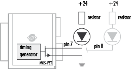
MOSFET transistors form the basis of the strobe amplifiers. The output signal is a PWM (pulse width modulation) signal with up to 3 amperes of current for the lighting for a short time. The duration of the illumination can be controlled with high precision in 15 ns steps.
SVS-Vistek leads the supply voltage as well as the input and power-out lines externally in the Hirose connector used as part of the 4IO concept.
By using PWM, there is almost no power dissipation in the camera, i.e. it does not heat up significantly by using the PowerOut outputs. The PWM signal regulates the illumination intensity with the integral of the current over time. Thus, the supply voltage is applied to the illuminant. If the maximum voltage or current is to be limited by circuitry, a shunt resistor must be connected in series with the illuminant.
The camera SDK provides access to all parameters of the controller. Light duration, current (more precisely: integral of the current over time) and, in conjunction with the built-in sequencer, delays and series can be switched. A configuration that e.g. the illumination only takes place during the exposure time of the camera is easily configurable and is then processed in hardware by the camera without further effort in the application.
Since the EXPOSURE signal of the camera does not have to be connected to the outside, jitter problems caused by external radiation are completely avoided.

Applications of 4IO in Machine Vision
The application range of the 4IO Strobe Controller is extremely wide and offers an alternative to external LED drivers wherever space is limited. With 4IO Strobe Controller you not only save additional devices (and costs) in your application, it also reduces the amount of cabling.
However, 4IO Strobe Control is limited in maximum power - for high power with several amps an external strobe controller may still be unavoidable.
Simple field wiring
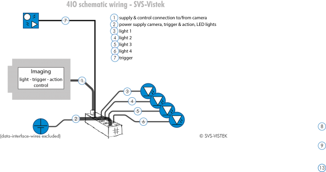
For easy and clear wiring of your applications, SVS-VISTEK also offers the Break-Out Box as an accessory. It can be used to intuitively connect lighting, camera, power supply and trigger lines to the camera. The connection is made via 3-pin sensor cables and meets the IP67 protection class.
In this way, 4IO Strobe Control helps to save cables, space and costs.
