Knowledgebase The Sequencer – The Feature
Cost-intensive and complex applications such as HDR can be realized with the Sequencer in no time and without additional modules. Potentiate the possibilities of the Strobe Control to multiple shots and save time, space and resources.
One feature for a thousand applications
The Sequencer offers the possibility to record an object in different settings. The object can thus be illuminated or exposed differently with a time delay. Thus, up to 16 intervals can be created that display the object differently.
SVCam Modelle mit Sequencer (44)The history of the Sequencer
Like so many things at SVS-Vistek, the Sequencer developed from a customer request. The goal was to illuminate an object from three directions. The resulting shadows were to be computed into a true-to-surface image of the surface. With the Sequencer, SVS-Vistek was able to produce these three images under the control of the camera. This eliminated the need for additional devices to control and supply the light, thus saving costs and significantly increasing the value-of-ownership.
Technology behind the Sequencer
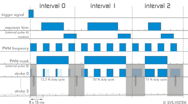
The Sequencer is the temporal extension of the Strobe Control. When a trigger is released, several Strobe Control intervals are processed one after the other. As with Strobe Control, the length of the intervals, the exposure and illumination times, the intensity of the individual illuminations and their underlying pulse width modulation can be selected.
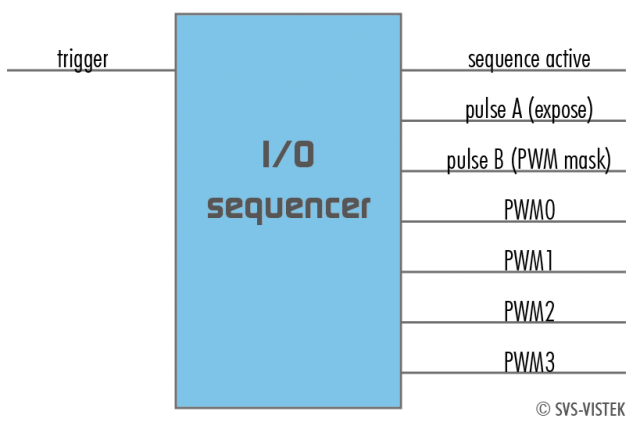
The Sequencer Module
All inputs and outputs are available at the IO Switch Matrix of the IOMUX.
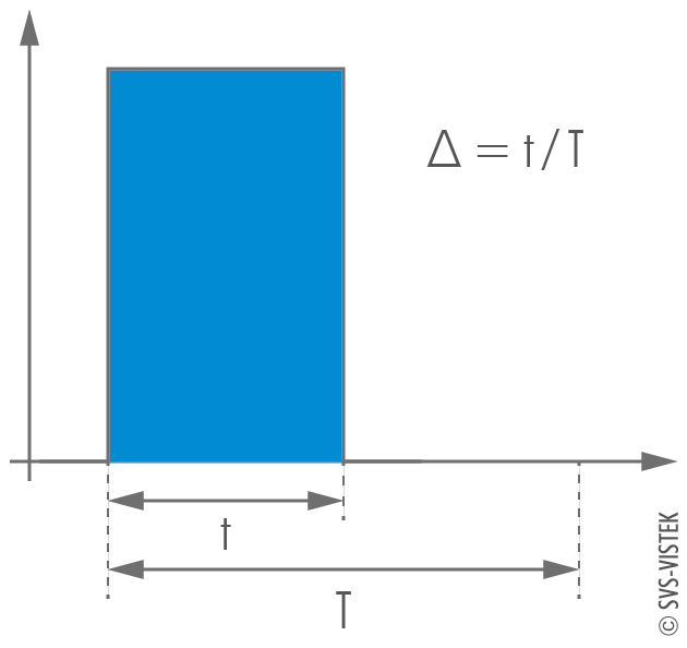
Pulse width modulation
The underlying frequency can be adjusted individually from interval to interval.
The setting is made by means of the period duration: "T" in 15 ns steps.
Select a short period duration to avoid harmonics.
The resulting intensity of the modulated pulse is calculated from t / T and is written to the register as PWM Change (specified as a percentage).