Knowledgebase Line Scan Camera - Endless Images for Machine Vision Inspection
Industrial Line scan cameras are the best solution for inspecting continuous materials or rolls by machine vision. Quite often they provide very high image resolutions and due to their speed demanding data rates.
Narrow strips joined to form a single image
Line scan cameras take only a single line as an image and send this to the computer. The host computer will assemble the lines. As this never stops, a virtually endless image is created. Line scan cameras are the perfect solution for inspection in print, textile production and with rotating or moving objects.
History of line scan cameras
Single-line CCD sensors capable of detecting dark and light first entered the market with the advent of fax machines. Indeed, most customary document scanners are still based on this principle. In this case, the sensor bar is located right beneath the moving object. With advances in sensor miniaturization and rising resolution, the sensors have increasingly moved further away from the object. Today, line scan cameras are integrated in customary camera bodies and can be operated with standardized lenses.
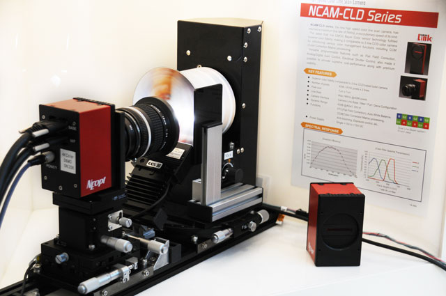
The optical setup of line scan cameras
Camera - object relation
Human eyes or a std photographic area camera takes an image with all pixels of the image at the same time, no distinction is made between still objects and moving objects. In one moment, all the image data is gathered.
Line scan cameras require either the camera or the object is moving. The size of the final image is determined by the camera's resolution in one axis, the other axis is determined by the number of lines the host computer is joining. There are two possibilities for a line camera setup:
- A stationary camera with material to be inspected driving by
- A moving camera with stationary material
The combination of moving camera and moving inspection material in most cases does not make any sense.
A line scan camera takes only one single line of the image at a time. As the material to be inspected is moving on, the next image taken will be the next line right close to the one before. As a result, a 2-D image taken with a line scan camera shows an image where every line of the image is taken at a different point of time. This is different to an image taken with an area sensor or the human way to perceive images and has implications for the machine vision software.
The lens of line scan cameras
In contrast to top-down document scanners, line scan cameras require optical systems. These are mostly identical to the lenses used with area sensor cameras. But, as the line scan cameras provide very high resolutions (up to 16k per line) the camera requires very high quality lenses with a decent MTF over the whole image.
Lighting of line scan cameras
Totally different to area cameras is the lighting setup. With the same line being taken (and the material driving by very fast) you need to illuminate only one line of the image. But, due to the speed of the material driving by (and the speed of the sequence of lines) exposure times are low, typically in the µs range. Consequently, line scan cameras very often require lighting setups with high or extreme light densities (up to 1000000 lux).
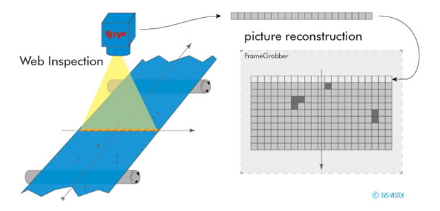
Reading and grabbing
As the sensor chip captures only a single line, it is easier to read the data held by a line scan camera compared with a large-area camera. It does not make any difference whether CCD or CMOS light-detection technology is used. As resolution is high and the objects are moving fast (thus joining lines is fast as well) the data rate typically is very high. You need a frame grabber to read the camera's data into the computer.
Line scan cameras require impulses
The decisive aspect in the use of line scan cameras is the ability to reconstruct the endless images. In a high frequency, many extremely narrow lines are combined into a single image. In the process of this recombination, it is important for the lines to be captured in sync with the object's speed as it passes by. In most cases, an impulse generator for the camera is integrated in the conveyor, generating the trigger signal for the camera. Like this, the camera's line frequency is adjusted in accordance with the speed of the object.
Multi-line scan cameras
Besides the (single-)line scan cameras being discussed until now, there are other flavours of line scan cameras as well
Multiline line scan cameras
Line scan cameras with 2 or more lines make greater demands of synchronicity. They can increase the maximum possible speed of the objects or improve the dynamics of the image in an HDR mode.
TDI CCD lines are extending the dynamic range of line scan cameras significantly already in the sensor itself.
Color line scan cameras
As with large-area cameras, line scan cameras can be fitted with monochrome or color sensors. The filters for red, green and blue are placed over the pixels as Bayer patterns or distributed over the lines to which a particular color is allocated and which are generally behind a filter. The resultant raw image is transmitted as monochrome information and then converted into a color image on the grabber.
Alternatively, 2 or 3 lines, each with a specific colour, might be used. This kind of setup challenging as the colours of the same pixel have to be taken with a object-related time difference. The benefit is a colour resolution with the sensor's full resolution.
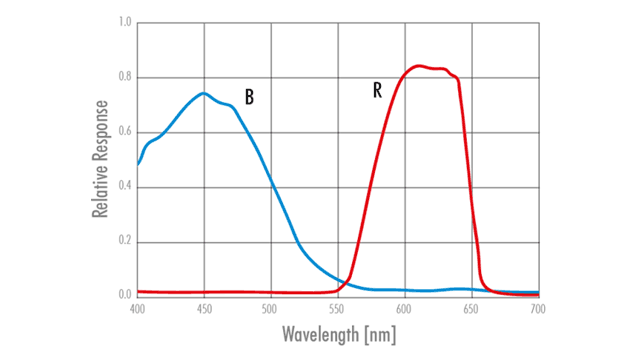
NEopt also offers the possibility of configuring its two-line cameras for only two colors. In this case, red and blue do not so much constitute two colors as two camera operations.
Data rates and resolution of line scan cameras
As is the case with large-area cameras, constraints are placed on the data rates of line scan cameras by the interface in industrial machine vision. Common interfaces i.e. are GigE Vision or Camera Link. This is calculated on the basis of the vertical resolution of the line (number of pixels in the line) and the number of lines per second, expressed as kHz / line per second.
Example: NCAM2-BLS with Cameralink: 8K pixels, 70 kHz
It generates 70,000 lines with 8,000 pixels per second. With a conveyor speed of 100 km/h and an object width of one meter, this translates into possible resolution of 0.122 mm per pixel latitudinally and 0.514 mm per line longitudinally.
optical resolution latitude: 100 km/h / 70,000 lines/s = 36 m/s / 70,000 line/s = 0.514 mm
optical resolution longitude: 1 m / 8,000 Px = 0,125 mm/Px
data rate: 70,000 lines/s x 8000 pixels x 8 bit = 560MB/s