Knowledgebase Polarization sensors
With the introduction of the polarization sensor, the world of Machine Vision has become richer by a new inspection method. Complex tasks such as surface inspection or the detection of stresses and particles in transparent materials are much easier to handle with a single image acquisition and some mathematical calculations without complicated light settings.
The Polarized Camera
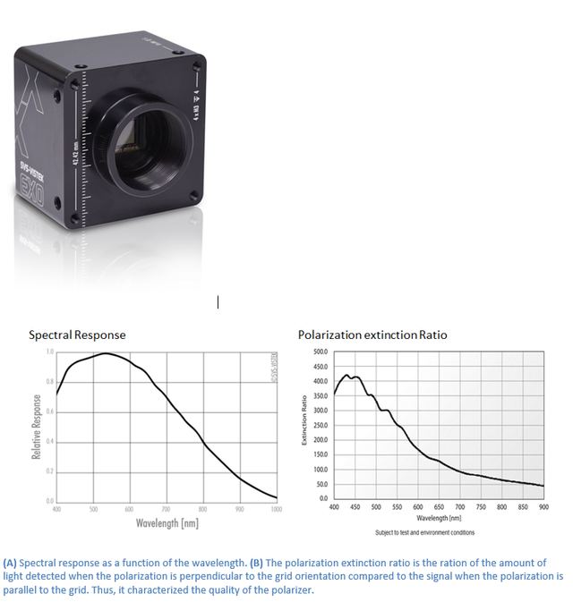
Along with brightness and wavelength, polarization is one of the fundamental properties of light. Our exo250Z camera with the new Sony IMX250MZR sensor can capture polarization information that cannot be detected by conventional imaging devices. This opens the door to new applications in machine vision and beyond. Prominent examples include analyzing the alignment of carbon fibers, visualizing stress in glass through stress-induced birefringence, reducing reflections and glare, or simply enhancing contrast between materials that are difficult to distinguish using conventional imaging modalities.
Polarization cameras (6)The physics
Machine Vision applications are often based on the automatic analysis of digital images. The images themselves contain information about the interaction of light with the materials in question. The type of information captured in the images depends on the image capture technology used. Digital monochrome or color cameras in combination with suitable optics are likely to be the most commonly used in machine vision systems. They capture the intensity distribution and, in the case of the color camera, additional information about the wavelength of the reflected or transmitted light of the objects of interest.
Light contains additional information that can be used to examine target objects. The electromagnetic waves of light are characterized by their intensity, wavelength, phase and polarization. With our polarization camera, information about the spatial distribution of the polarization state of light can actually be captured.
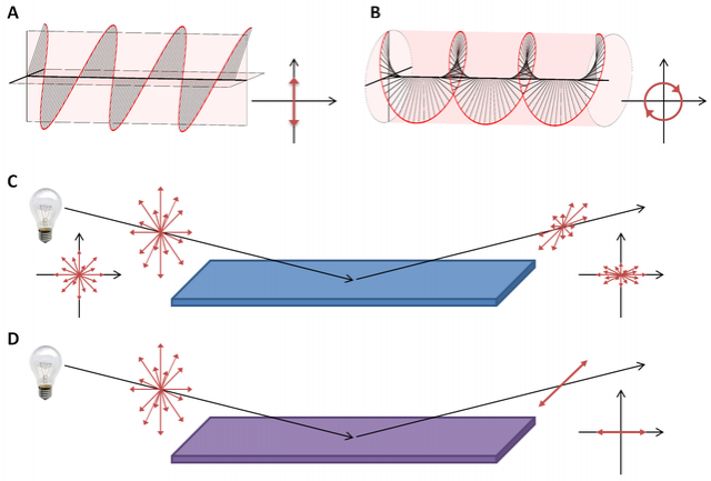
Polarization is a property that characterizes the geometric orientation of the oscillation of the electric field of light. Linearly polarized light, for example, is light that oscillates only in a plane perpendicular to the direction of propagation. Figure 1A shows a linearly polarized wave with one wavelength. In addition, the figure shows circular polarization (Figure 1B). It can be obtained, for example, by transmitting linearly polarized light through optically active media [1]. Here we will mainly focus on linearly polarized light.
The light we encounter in our natural environment from most common light sources is generally unpolarized, i.e., the light consists of a large number of waves with statistically distributed directions of oscillation (see Figure 1C, left). An interesting effect occurs when this unpolarized light is reflected from dielectric materials such as glass. These materials exhibit different reflectivity for polarization components polarized parallel to the surface normal of the material compared to components polarized perpendicular to it. The difference in reflectivity depends on the material's reflectivity index as well as the angle of incidence. Therefore, the reflected light usually exhibits partial polarization (Figure 2C, right). Incident light at a certain angle, called the Brewster angle, has the interesting property that only polarization components perpendicular to the surface normal are reflected, resulting in linearly polarized reflected light (Figure 1D).
[1] In simple terms, linearly polarized light can be thought of as an addition of two coherent waves in two orthogonal directions. An optically active medium may have a different refractive index for polarizations along these two directions, so that the two partial waves propagate through the medium at different speeds and acquire a phase difference. The addition of these two phase-shifted waves results in elliptical or circular polarization because the resulting electric field vector assumes an elliptical or circular pattern (Figure 1B). Circular polarization occurs when the phase shift is exactly 90°.
Measuring polarization
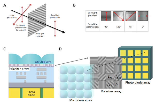
To characterize the polarization of light, linear polarizers can be used. They are a simple and efficient way to obtain linear polarization from unpolarized light. There are a variety of polarizers, and it is beyond the scope of this article to explain them all. Here we will focus on the grating polarizer. This is an optical element consisting of an array of parallel metal nanowires below the wavelength. The component of the incident electric field that is polarized parallel to these metal wires is blocked so that only the polarization components that are perpendicular to the nanowire grating are transmitted (Figure 2A). These nanowire gratings are used in our exo250Z camera.
Our exo250Z camera series uses the newly developed IMX250MZR sensor from Sony. This sensor is based on the popular 2/3" IMX250 CMOS sensor with a pixel size of 3.45µm. A square polarizing filter array with four directions is located directly above the pixel array and below the microlenses (Figure 2C, D). This filter consists of repeated 2x2 patterns made up of grating polarizers with four different angles at 0°, 45°, 135°, and 90° (Figure 2D). Each polarizer filters the incident light so that only the polarization components that are perpendicular to the orientation of the grating can pass through and be detected by the underlying photodiode. In this way, an image with four polarization directions can be captured in a single image.
Application of Mathematics
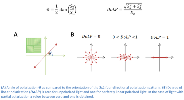
In subsequent post-processing, this image can be used to obtain four images filtered with one polarization filter each. In addition, the images can be used to estimate the spatial distribution of the brightness of each 2x2 pattern by averaging, as well as the associated linear polarization angle and the degree of linear polarization (Figure 3).
The pixel intensities of a 2x2 pattern are a measure of the fraction of light with 90° ( I90), 135° (I135), 45° (I45), and 0° (I0) polarization, respectively (Figure 2D). The addition and subtraction of these intensities are called Stokes parameters[1]:
S0 = I0 + I90
S1 = I0 - I90
S2 = I45 - I135
Practically, the polarization angle PHI and the degree of linear polarization can be easily calculated from the Stokes parameters[2]:
Examining these values leads to an improvement in image contrast compared to conventional camera images in a variety of applications, as shown in the following application examples.
[1] Please note that the fourth Stokes parameter, which is calculated from the intensities of right and left circularly polarized light, cannot be obtained from the image.
[2] The inverse tangent must be calculated to obtain values in a closed interval.
Application examples
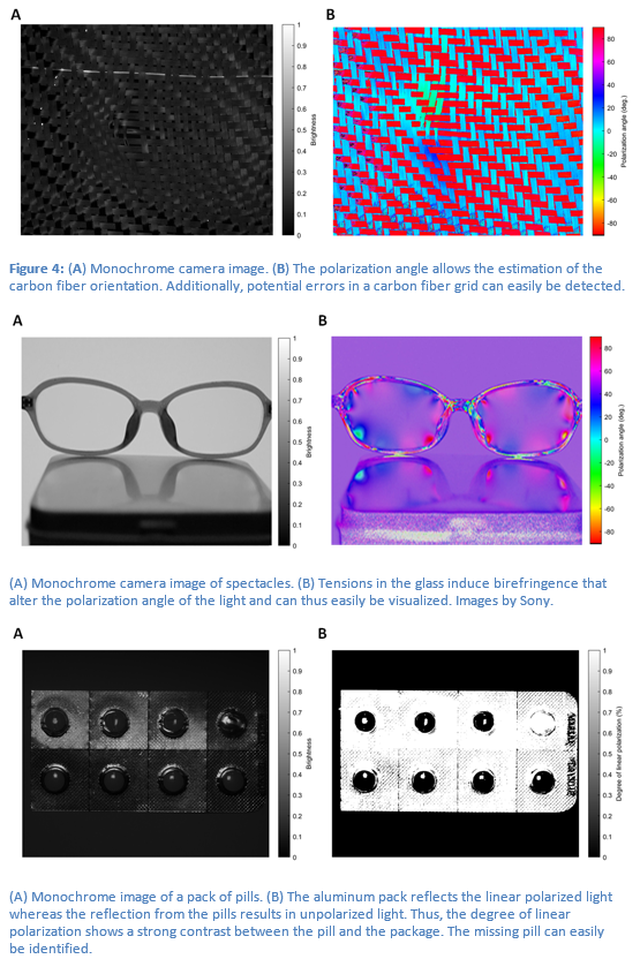
The calculation of the spatial distribution of the polarization angle as well as the degree of linear polarization increases the information content of the measurement. There are many applications for such measurements, such as analyzing the alignment of carbon fibers, visualizing stresses in glass through stress-induced birefringence, reducing reflections and glare, or simply improving contrast between materials that are difficult to distinguish using conventional imaging techniques. Some application examples are listed below.
The Polarized Camera
The EXO series polarized is available with USB3 interface and with GigE vision interface. In terms of optical properties (polarization), both cameras are identical. Choose the best interface for your application.